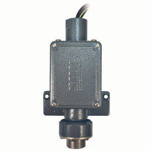
Big Hermet pressure switches are robust field-mounted instruments. The pressure sensing assembly is identical to a conventional Static “O” Ring type. The main difference is that the witching element assembly is hermetically sealed in a steel capsule. Switching elements are SPDT or DPDT. A description of the operating principle can be found on page 2.
Application Information
The pressure switches in this catalog are suitable for a variety of process applications in hazardous locations and hostile environments. Basic models with standard wetted parts are normally suitable for air, oil, water and non-corrosive process fluids. See the Quick Selection Guide on page 4. Corrosive service and particle user requirements may require optional components. See How to Order on page 3. More hostile environments, space restrictions and user preference may require Mini Hermet models. High pressure fluid power (hydraulic) applications where high shock pressures and high cycle rates are expected normally require pivot seal type pressure switches.
(Refer to Form 219.)
Features and Benefits
Robust Construction
- High cycle rate tolerance, long life, not critical to vibration, protected internal hermetically sealed switching element capsule.
Instrument Quality
- High resolution of Set Points, high repeatability, narrow dead band, negligible temperature effect, high overrange and proof pressures.
Explosion-Proof Hermetically Sealed Switching Element Capsule
- Isolates switching elements from corrosive, hostile and hazardous environments and virtually eliminates problems from corrosion. Field Adjustable Set Points
Full range adjustability without disconnecting electrical power while maintaining explosion proof integrity, self-locking adjustment, no special tools required, no-charge factory
calibration.
Cost Effective
- Simple and fast installation without special tools, long service life.
Agency Listings/Certification
- Select models with RTN, SIL, UL/CSA, TestSafe (SAA)
- Meets most code and customer requirements
Safety Certified to IEC 61508 (SIL)
SOR products are certified to IEC 61508 for non-redundant use in SIL1 and SIL2 Safety Instrumented Systems for most models. For more details or values applicable to a specific product, see the Safety Integrity Level Quick Guide (Form 1528).
Built-In Quality
Rigid quality standards maintained from raw material to finished product.
Delivery
Routine shipments 7 to 10 working days.
Emergency shipments via same day.
Service
Factory service engineers and area factory representatives provide effective and prompt worldwide service.
Warranty
3 years from date of manufacture

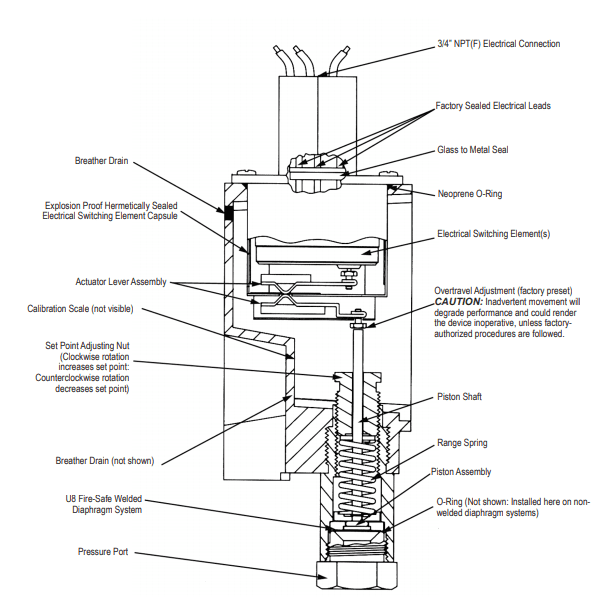
The pressure sensing element of the SOR Pressure Switch is a force-balance, piston-actuated assembly. The sensing element is sealed by a flexible diaphragm and a static o-ring. There are only three wetted parts in this arrangement: a pressure port, a diaphragm and an o-ring. A wide selection of wetted parts materials for media compatibility and containment is available. A metal diaphragm may be welded to the pressure port for certain applications, thereby eliminating the o-ring (designators U7, U8 and U9).
Media pressure on the piston counteracts the force of the range spring (adjustable by the adjusting nut) which moves the piston shaft only a few thousandths of an inch to directly actuate the electrical snap-action switching element that is enclosed in the hermetically sealed steel capsule. This design results in low friction and virtually no wear. The electrical switching element is isolated from corrosive atmospheres.
Basic Big Hermet pressure switches with standard wetted parts are normally suitable for air, oil, water and non-corrosive process in hazardous locations and hostile environments. The Set point must be within the adjustable range. Refer to How to Order section on page 3 to locate optional components. Each position in the model number, except Accessories, must have a designator.
Pressure Switches
| Model Number | Adjustable Range psi (in. wc) |
Typical Dead Band psi (in. wc) |
Overrange psi |
Proof psi |
| 12BA-KB614-N4-B1A 12BA-KB2-N4-B1A 12BA-KB4-N4-B1A 12BA-KB5-N4-B1A 12BA-KB45-N4-B1A |
(10 to 45) 0.4 to 2 0.5 to 6 0.75 to 12 1 to 16 |
(1.2) 0.15 0.2 0.2 0.2 |
200 | 400 |
| 4BA-KB2-N4-B1A 4BA-KB4-N4-B1A 4BA-KB5-N4-B1A 4BA-KB45-N4-B1A |
2 to 8 2 to 25 3 to 50 4 to 75 |
0.3 0.5 0.7 0.8 |
750 | 1000 |
| 6BA-KB2-N4-F1A 6BA-KB3-N4-F1A 6BA-KB5-N4-F1A 6BA-KB45-N4-F1A |
7 to 30 12 to 100 20 to 180 25 to 275 |
0.8 1.3 2 3 |
1500 | 2500 |
| 5BA-KB3-N4-F1A 5BA-KB5-N4-F1A 5BA-KB45 -N4-F1A |
25 to 240 35 to 375 45 to 550 |
3 4.5 6 |
||
| 9BA-KB4-N4-F1A 9BA-KB5-N4-F1A 9BA-KB45-N4-F1A |
100 to 500 200 to 1000 200 to 1750 |
10 14 23 |
5000 | 6000 |
Vacuum Switches
| Model Number | Adjustable Range in. Hg (in. wc) (vacuum to pressure) |
Typical Dead Band in. Hg (in. wc) |
Overrange psi |
Proof psi |
| 52BA-KB116-N4-B1A 52BA-KB117-N4-B1A |
(20 - 0 -20) (40 - 0 - 40) |
(1.4) (1.6) |
200 | 400 |
| 54BA-KB117-N4-B1A 54BA-KB118-N4-B1A |
15 - 0 - 15 30 - 0 |
0.7 0.9 |
750 | 1000 |
| 56BA-KB216-M2-F1A 56BA-KB316-M2-F1A |
30 - 0 - 20 30 - 0 - 160 |
1.5 2.1 |
1500 | 2500 |
Standard Construction
1. Housing: BA-Aluminum. See housing and dimensions pages for details.
2. Switching Element: KB-SPDT 15a 250 VAC. See page 7 for optional switching elements.
3. Diaphragm & O-Ring: N4-primary (wetted) diaphragm TCP, o-ring (wetted) Buna-N. See below for optional diaphragm and o-ring systems.
4. Pressure Port: B1A-Aluminum 1/4” NPT(F); F1A-Carbon steel 1/4” NPT(F). See below for optional pressure ports.
5. Dead Band values are expressed as typical expected at mid-adjustable range with the standard KB switchingelement installed.
Design and specifications are subject to change without notice. For latest revision, see SORInc.com.
This table is a listing of piston-spring combinations and the corresponding adjustable ranges, dead bands, overrange and proof pressures. Adjustable range is expressed for increasing pressure; the Set Point must be within the adjustable range. Dead band is expressed as typical. See dead band considerations at the bottom of switching element.
| Piston-Spring Designator |
Adjustable Range | Typical Dead Band | Overrange | Proof | ||||
| psi (in. wc) | bar [mbar] | psi (in. wc) | bar [mbar] | psi | bar | psi | bar | |
| 12 - 614 12 - 2 12 - 4 12 - 5 12 - 45 |
(10 to 45) 0.4 to 2 0.5 to 6 0.75 to 12 1 to 16 |
[25 to 110] [30 to 140] [35 to 415] [50 to 830] [70 to 1100] | (1.2) 0.15 0.2 0.2 0.2 |
[3] [10] [14] [14] [14] | 200* | 13* | 400 | 27 |
| 4 - 2 4 - 4 4 - 5 4 - 45 |
2 to 8 2 to 25 3 to 50 4 to 75 |
[140 to 550]
0.14 to 1.7 0.2 to 3.5 0.3 to 5 |
0.3 0.5 0.7 0.8 |
[20] [35] [48] [55] | 750 | 50 | 1000 | 70 |
| 6 - 2 6 - 3 6 - 5 6 - 45 |
7 to 30 12 to 100 20 to 180 25 to 275 |
0.5 to 2 0.8 to 7 1.4 to 12 1.7 to 19 |
0.8 1.3 2 3 |
[55]
[89]
0.14 0.21 |
1500 | 100 | 2500 | 175 |
| 5 - 3 5 - 5 5 - 45 |
25 to 240 35 to 375 45 to 550 |
1.7 to 16 2.4 to 26 3.1 to 38 |
3 4.5 6 |
0.2 0.3 0.4 |
||||
| 9 - 4 9 - 5 9 - 45 |
100 to 500 200 to 1000 200 to 1750 |
7 to 35 14 to 70 14 to 120 |
10 14 23 |
0.7 0.9 1.5 |
2500 | 175 | 6000 | 420 |
| 1 - 45 | 500 to 4000 | 35 to 275 | 150 | 10 | 5000 | 340 | 6000 | 420 |
Piston Spring
Notes
1. Dead Band values are expressed as typical expected at mid-range with the standard KB switching element assembly installed. When optional switching elements are specified, corresponding dead band multipliers must be applied.
2. Special ranges may be possible. Consult the factory or the SOR representative in your area.
3. Diaphragms may have an effect on dead band. Consult factory.
4. Design, operating and rating specifications are based on English psi (in. wc) engineering units rather than metric values. This data appears on the product nameplate when English engineering units are specified.
5. Metric bar (mbar) values are practical equivalents of the reference English values; not necessarily exact mathematical conversions. This data appears on the product nameplate when metric
engineering units are specified.
*CAUTION: Overrange for UL Listed/CSA Certified pressure switches with the BL housing and the U8
diaphragm system is reduced to 100 psi (7 bar).
This table is a listing of piston-spring combinations and the corresponding adjustable ranges, dead bands, overrange and proof pressures. SOR vacuum switches are compound; they will operate in either vacuum or pressure modes. Adjustable range is expressed from maximum vacuum decreasing to zero gauge and increasing to maximum pressure. Dead band is expressed as typical. See dead band considerations on bottom of page 7. The Set Point must be within the adjustable range. A vacuum switch is generally better suited than a pressure switch for Set Points very near zero gauge.
